
 DFMA: SHOULD COSTING
 DFMA: PRODUCT SIMPLIFICATION


ITT Slashes Valve Costs with DFMA
HOW TO MANUFACTURE SUCCESS:
HERE’S YOUR PLAN…
By David M. Vranson
Advanced Manufacturing Engineer
ITT Control Technologies
Aerospace Controls
A Plan for Manufacturing Success
It's all about revenue and profitability. The basis for a healthy productive enterprise and economy is the sustainable manufacturing of durable goods. Having a solid plan is absolutely necessary for creating a successful manufacturing venture. The operative word here is “sustainable”. So to successfully launch a product into the market, you have to carefully plan for it and know where you want the plan to arrive at.
Neglect this facet of doing business and you will likely arrive at a destination you hadn’t anticipated. Somewhere in the unstructured, creative act of product development, the original business intention can become obscured: you need to make the product and be able to sell it at a pre-determined profit. When a manufacturing project plan is created at the early product development phase, the project now becomes goal oriented.
Cost Out
Like it or not, this phrase is actually payment for a big mistake. It’s becoming increasingly used throughout our industries to describe an activity that should not have to happen.
See if you can relate to this scene: You are at a discrete meeting thrown by the Director of Operations. You’re all gathered together. There are representatives from all walks of life that make your manufacturing enterprise tick. They begin by describing the previous three months of financial data surrounding one of your company’s prime products. The data is not favorable. This product has shown to be very expensive to produce. The cost of the parts is high and continues to increase. The parts are difficult to assemble and are creating an inefficient operation. You struggle with making your delivery commitments and the product is frequently the top hitter of your “On Time Delivery” performance metric.
As discussion buzzes around the table and opinions about the cause are brought to the surface, you soon are assigned to do a “Cost Out” project on this product. They want you to seek out the causes of the unnecessary expenses, the waste, and remove them from the environment. There…You now have a monkey on your back.
Cost Out, or whatever you choose to call it, is a second-effort exercise. Simply put, it is rework. Reworking of what is wrong with the product, or with the process that is meant to produce it. The Cost Out project entails figuring out what is the cause of the waste and determining the effort and expense to remove it. More often than not, the design needs to be significantly revised to accommodate the goal to make money from selling the product.
Will Lean methodologies help? They will to an extent. But don't make the mistake of trying to use Lean to remove waste that is designed right into the product. You can momentarily mask an inefficient-to-manufacture design, and struggle to hold the line. But it won't sustain because no tangible improvement has been made. Only a change in the manufacturability of the design will sustain process improvement.
Once an inefficient design is released and hits the production floor, the source of the designed-in inefficiency tends to become invisible and manufacturing now yields to the inefficiency, taking on full responsibility as it enters the world of recurring cost. Let the battle begin! Engineering wants the product built as-designed (the non-recurring cost activity is shut off) and declares that manufacturing operations needs to lean out the waste and get the production cost on track.
What a Plan for Manufacturability Looks Like
Design for Manufacturability – To proactively design the product and assure the best cost, quality, reliability, delivery and customer satisfaction, use design for manufacturability to optimize all your manufacturing functions: fabrication, assembly, test, procurement, shipping, delivery, service/repair and warranty.
The “BHAG” – Or Big Hairy Audacious Goal. Set it as a stretch out of what is usually considered during a product development exercise. If the product, for example, is to compete or better an existing baseline or benchmark, your BHAG might include reduce the part count by 50%, or reduce the overall product cost by 50%. Or if delivery is your demon, design so as to build 1000 units per day, where only 400 or 500 were produced before. Make BHAG a chance for a slight breath-taker. It's okay to set goals like that. Remember it's just a plan but reach out and try to get there.
“PDQ” – Price, delivery and quality. The plan for success will focus on customer-valued features and the elements of a plan should include some modern basics to take advantage of current and proven technology.
Price, delivery and quality are the basic building blocks of a design plan because these are what the customers will be paying attention to. You can throw safety into the mix as well if it applies. The PDQ targets come below the BHAG but are equally as important and should be considered as “must do” elements. Know what your competitive price should look like at the end of the project. What is the daily takt rate/time supposed to be to meet the marketing analysis? What customer valued features are to be included to produce a reliable product (perceived quality level sustains return business). Remember…planning for PDQ starts as soon as possible in the design cycle!
Minimize the need for Lean Methodology – Well, believe it or not, the Lean Seven Wastes are a great place to start a plan off (after you’ve selected the BHAG). Minimize these and the Production & Operations folks will begin to look at you like their hero. Waste is what they will be looking to avoid after the design is released. Why not design them out of the product before it’s released for production? Most of us in this business have been made well aware of seven wastes, but they can be used for the plan for manufacturability:
Overproduction – Overproduction is producing products or parts before they are actually needed, thereby preventing the smooth flow of materials. It causes batching, degraded quality and disruptions.
Waiting – Batch-and-queue manufacturing leads to materials waiting to be processed which will consume most of the product’s manufacturing life. Plan to design your products so this can be prevented…minimize processing at each workstation or manufacturing step.
Inappropriate Processing – Designing processing outside of current capability can cause materials to be processed on equipment or within facilities that are beyond what’s really necessary to create functional parts. Plan to produce with equipment suited to the job. Budget to purchase new equipment if required.
Unnecessary Inventory – Inventory, especially what isn’t required at the moment, will do only one thing to your cash flow…and it isn’t pretty. Excess inventory is a direct result of overproducing and waiting. Think about this issue when designing products. The easiest way to reduce inventory through design? Cut the part count. Use the money for better things!
Unnecessary / Excess Motion – Mainly dealing with the human element of production, excess motion can lead to fatigue and overuse injury. Designing in repetitive motion or the need to move and manipulate the products in production greatly reduces manufacturing efficiency and consumes cycling time. Designing in processes that require excursions to an otherwise out-of-sequence operation…like oven-curing of adhesives or sealants…causes the need for movement.
Defects – How do we design for zero or minimize defects? If you can reduce the part count, you’ll take care of this one without even having to think about it. At a minimum, reducing all the other six wastes will help eliminate opportunities for damage. Basically design for minimal processing and movement will benefit the throughput.
Transporting – Consumes resources unnecessarily. Allows opportunity for parts to become damaged and consumes cycle time. Designing with materials that require outside processing necessitates transportation.
Concurrent Engineering
Concurrent Engineering has become an essential element within product development activity. The multiple disciplinary roles create the manufacturability plan based on the experience and working knowledge each member brings to the circle. Concurrent Engineering is a proven design methodology that works for any size company. Early consideration of manufacturing shortens development time, minimizes development cost, and allows for a smooth transition into production.
Plan for the Attributes of Manufacturability
The attributes of manufacturability are those that introduce design elegance. Simplicity. Minimalistic without any degradation to customer value. Generally, the customer is not going to be concerned with the attributes directly, since they largely help internally with material velocity, cost control, and an increase in manufacturing efficiency. However, the customer will notice the PDQ part. The designed-in attributes include:
Part count reduction – Use as few piece parts as absolutely necessary to achieve function and quality.
Ease of part handling at the point of assembly – Try not to use components that nest or tangle together prior to assembly. Avoid parts that are difficult to grasp without the use of tools.
Ease of part insertion into the assembly – Use of a single axis of insertion for all components eliminates assembly reorientation…and use gravity as a tool…it’s free! Try to eliminate point of insertion view, access, or alignment difficulties.
Minimal use of tools (if any) – Nearly all fasteners use tools to install, so aim to eliminate separate fasteners. Don’t design in adjustments so that the assembly can work. Assembly aids other than hands add to the time it takes to put things together.
Minimal use of standard or special processing – Design in materials that don’t require outside processing such as plating or painting. Keep drilling and machine work off of the assembly line!
Essential Tool of the Trade
An essential tool for arriving at design elegance is DFMA®, or Design for Manufacture and Assembly. Divided into two basic modules, Design for Assembly (DFA) and Concurrent Costing or Design for Manufacture (DFM), this program is used to analyze your design and score it in terms of manufacturing efficiency. It’s not a magic bullet, but it is way ahead of whatever is in second place. The sequence of preferred use would be to analyze your baseline (or benchmark—whichever you prefer) assembly using the DFA module. Using this first will assist in the elimination of part count and minimize your processing design up front. Subsequently using the Concurrent Costing module on the parts remaining will provide for optimal design, taking advantage of technology to arrive at the most cost-effective methods to fabricate the parts of the assembly. As shown below, use of the DFMA program aids in rapid decision making that is essential for competing within your marketplace.
Case In Point
An illustration and simple example of what a clear and focused product development plan will provide at the manufacturing outcome can be shown in a small project our company undertook. In typical form, a customer approached and requested a proposal to replace an existing valve within a system aboard their commercial aircraft fleet. There are 3 of these valves per aircraft and they fit into a 7 inch air duct system.
A small design team was assembled, reviewed the requirements and found there was an existing design that might fulfill the application. But there were several issues getting in the way of proceeding forward with the proposal. For starters, the design was quite old…roughly 30 years or more. Although it would work fine in the system, the manufacturing technology had drastically changed since the valve was designed. This led to the second issue: Cost. The valve body and butterfly assembly were incredibly expensive in today’s manufacturing world. After a pricing exercise was completed, the choice was clear: It was time for a new design.
Using the existing design as a baseline, a DFA analysis was run to find where the cost hardships were. Although the material costs were reason enough to engage new design activity, the analysis showed a very poor manufacturing efficiency. The results of the analysis provided the targets for improvement using the “Suggestions for Redesign” report function from the software. This report is useful in that it provides the calculated percentages of improvement for various elements based on the bill of materials and processing requirements.
Knowing what was detracting from attractive attributes of manufacturability, the designers now went to work on creating a configuration that contained a minimal amount of parts to get the function the customer expected while making the product easy to assemble as well. Though this is a fairly straight-forward type of valve design (simple), the results of the exercise were fairly dramatic.
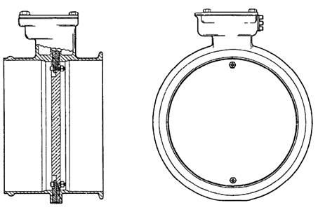
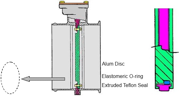
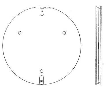
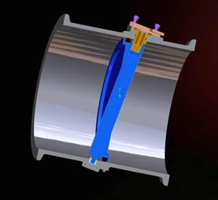
The most important changes were made to the valve body, the butterfly assembly and how it sealed against the inner wall of the body. The old body design involved multiple machine set ups on different machine types and required special attention to the interior surface finish, honing the sealing area against a tightly toleranced inside diameter. The butterfly assembly employed a multiple-featured groove around the outside diameter in which an elastomeric O-ring was used to back up an extruded Teflon seal. The seal was approximately 21 inches in length and needed to be fed into a machined groove against the pressure of the O-ring backing (see figure 1), requiring pushing and pulling it around the butterfly disc during installation and cut to size. If the seal became damaged in any way prior to installing the assembly into the body, the seal was pulled out and replaced.
Our design for manufacturability plan was simply this: Design a suitable valve with as few parts and manufacturing processes as possible, that would assemble quickly and with a level of quality and reliability that would exceed our customers’ expectations. And what resulted from that vision was exactly what we set out to do.
Several design change scenarios were loaded into the DFMA program and the calculations showed dramatic changes to the attributes of manufacturability. After several iterations of this exercise, the final redesign activity took place. Using the calculation results, a proposal was put in place and accepted by the customer. The following illustrations show the results of the redesign.
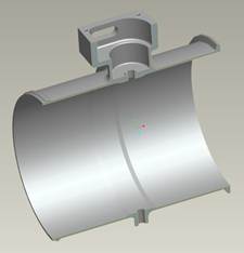
For the new design, the focus was first on the high-dollar items only because their cost was highly illuminated. These items were the machined aluminum valve body and the butterfly disc assembly. Since these two items met the DFMA criteria for the theoretical minimum, the need to simplify both was apparent and since this was to be considered a new product development, there were few constraints on the design. The expense in the butterfly disc was the configuration of the groove that retained the seal components, and the cost of assembling it. The expense in the valve body was the over-all form and the method of fabrication. In that the old design was shaped the way it was, machining it from a rectangular billet at the time was considered more economically suitable. Today’s technology changed all that. The resulting update is seen in figure 3. As opposed to machining a rectangular billet, the newer design can be machined out of a near-net size round form allowing a single set up on mill-turn equipment.
Without surprise, the newer design will cost about 20% of what it would cost to fabricate the old design. Though not as dramatic, the Butterfly Disc rings in at a cost of about 60% of what the original would cost. Both the Disc and the body components were compared first using the Concurrent Costing module of the DFMA program to verify the design was headed in the right direction. The resulting calculation percentages were very close. The calculated values were validated and followed up with supplier and in-house quotations.
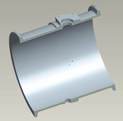
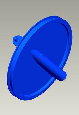
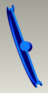
As seen in Figure 4, the newer Butterfly Disc appears more complex, but the processing is ultimately easier on more modern multi-axis machine tools. Again, fewer set ups have saved the day.
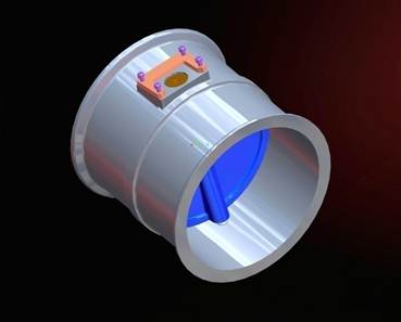
Not only is the improved seal design much easier to assemble, it has an improved function in that the seal becomes tighter when pressure is increased. And, because it uses only the elastomeric interface against the interior wall of the valve body, the surface finish of the aluminum becomes less critical, eliminating unnecessary machine processing (honing), and dimensional tolerances loosened up. Figures 5 and 6 show the new valve assembly.
| Original | Improved | Reduction | |
|---|---|---|---|
| Part count | 27 | 14 | 48.1% |
| Assembly time (min) | 8.08 | 2.54 | 68.6% |
| Material cost | $5,124.67 | $1,199.56 | 76.6% |
| Labor cost | $3.95 | $1.24 | 68.6% |
| Tooling cost | $0.25 | $0.00 | 100.0% |
| Total cost | $5,128.87 | $1,200.80 | 76.6% |
| DFA Index | 3.1 | 10.4 | — |
Quantified by DFMA analysis and validated with supplier and in-house quotations.
Takeaways
Of course, the goal here was to reduce the cost of the finished assembly to a level where a competitive proposal could be submitted to our customer. That goal was certainly met through a successful plan for manufacturability. But should cost be considered an attribute of manufacturability, or an outcome of design for manufacturability? Cost avoidance or reduction is a resulting benefit of simplifying a design.
Do not design (or re-design) a product solely with a focus on reducing the cost. Doing that can lead your team down the wrong trail and manufacturability can be overlooked. So, our focus was on design simplification and the elimination of waste to production. Plan on providing those two qualities and any unnecessary product cost will go away automatically as a secondary benefit.
| Discover | Learn | BDI Info | Follow Us |
| Software | Studies | About BDI |

|
| Solutions | Webinars | Contact |

|
| Training | News | Directions |

|
| Services | Papers | Agents | |
| Support | Forum | Partners |
DFMA and Concurrent Costing are registered trademarks of Boothroyd Dewhurst, Inc.
© Boothroyd Dewhurst, Inc. All rights reserved. Privacy Statement.