|
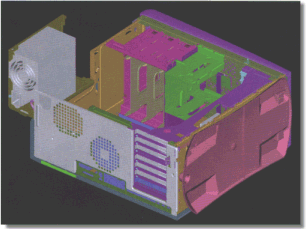
Dell Builds a Framework for Success Design for Assembly and Design for Service drive the design of Dell Corporation’s Optiframe® Computer Chassis. Dell Computer Corporation (Round Rock, Texas), the world’s leading direct computer systems company, has long been recognized as a provider of easily serviced, readily installed, customized computers. By 1998, Dell was associated as well with something else—an explosive growth 2.5 times the industry average. Customized assembly of computer equipment requires operators, time, and space. Dell was glad that customers were enthusiastic about its products, but the company balked at the physical and personnel expansion that would be needed to meet the increasing orders. “Brick and mortar are expensive,” says Bradley Keup, a systems engineer at Dell. “So are added personnel.” Instead of adding facilities and people, the company took a less-expensive route: it redesigned its products to make them easier and faster to assemble and to service. In fact, redesigning one product, the Optiframe® chassis for personal computers, saved Dell an estimated $15 million dollars in reduced direct labor costs. The company saved millions more by increasing throughput and thus postponing facility relocations that otherwise would have been required to boost manufacturing capability. The savings in materials cost from chassis integration and the related supply chain optimization program was $11.6 million for 1998 and is predicted to be $35 million in 1999. For a single design project, these are impressive savings. The Optiframe design challenges The goals that the Optiframe design team set for product and process design were no less impressive:
Dell accomplished all of these goals through a methodology they call DFX, or design for X. Design for Assembly (DFA) and Design for Service (DFS) design analysis software from Boothroyd Dewhurst, Inc. (Wakefield, R.I.) are fundamental to this methodology.
The DFX design team includes representatives from procurement, manufacturing engineering, manufacturing quality, customer service, process engineering, new product engineering, supplier quality engineering and logistics. Membership from a wide range of expertise promotes early design definition and ensures manufacturability up front in the product development cycle. To the DFX team, metrics are all-important. They drive operational and product goals, provide benchmarks, and allow the team to evaluate results impartially. “Our slogan,” says Doug Dewey, a DFX engineer, “is ‘If you can’t measure it, you can’t control it.’ Once metrics define product characteristics, we can set goals and measure our design progress against them.” DFX metrics at Dell measure throughput, time and cost, and they are defined and implemented through several tools. Among these tools, DFA and DFS software are critical for establishing metrics and for promoting concurrent design evaluation and innovation. DFA software enables engineering design teams to evaluate the functional purposes of each assembly component in a conceptual design. Data accumulates as the engineers answer three questions about each part in the product and its assembly sequence:
Once the designers answer these questions, the software produces a summary report of a theoretically attainable optimum design. The DFA software then guides the engineer in rating each component on its ease of orientation and assembly. Finally, the software generates estimates of total assembly time and costs. Dell uses these estimates to help build its design metrics. DFS software focuses on the disassembly sequence required to service components in the design assembly. Data transfers directly from the DFA structure chart to the DFS disassembly worksheet. The resultant data provides a time estimate for disassembly and reassembly, from which the software arrives at cost estimates for service. “DFA and DFS software were key tools in setting first-pass initial goals for our Optiframe project,” Keup says. The team used the software to evaluate the designs of existing products—both Dell’s and their competitors’—and to establish benchmarks. Keup says, “Benchmark and competitive analysis is a huge part of our job. We have design data bases on nearly every product that our major competitors have released in the last six months.” In addition to setting achievable design goals, the team established metrics for product throughput. Based in part on the estimated assembly and disassembly times and on cost data derived from DFA and DFS analysis, the team was able to establish metrics for units assembled per hour per operator, direct labor costs per unit, mean time to repair, and even units assembled per hour per square foot of shop floor. This last metric was fundamental for meeting throughput goals that would enable Dell to avoid costly plant expansion and relocation. Design review process During basic layout review of the Optiframe design, data from the Boothroyd-Dewhurst software analysis was linked to an animated model on Dell’s intranet so that worldwide design and process teams could shape the product and the process concurrently. “Our electronic product models provide motion so that the team can see the characteristics of part assembly and disassembly, clearances and orientation,” Keup says. “In design analysis, if a picture is worth a thousand words, an animated model is worth a thousand pictures.” The design team incorporated suggested changes in the model, creating multiple iterations of virtual prototypes throughout the DFX stages of concurrent design and process development: CAD and Process Modeling, Concept Layout and Process Tool reviews, and Final Design and Manufacturing Process reviews. At each stage, the designers conducted DFA and DFS analyses of the evolving model. Keup notes, “By using DFA throughout the design process, we found ways to streamline the product still more.” For example, during virtual prototyping, process engineers identified assembly points that would cause manufacturing bottlenecks, and the design engineers focused on redesigning those areas. In this way, redesign for reduced part count and assembly time also resulted in the greatest time savings on the production line. Innovations in the new Optiframe design included a hard drive bracket that rotates out of the chassis for drive assembly and a patented hinge-lock mechanism on the stand for the power supply. The hinge-lock allowed a supplier to install the power supply ahead of time, which cut Dell’s assembly time nearly 40 percent. Another time-saver for assembly is the patented hook-and-lock retention system for the mother board. The system requires only one fastener, a vast improvement over most competitors’ designs. But it’s the tool-less cover, a product of DFS analysis, that provided the greatest reductions in disassembly and reassembly times. “The cover rotates up and allows a customer a top-down look into the chassis within ten seconds, without his needing to use a screw driver or any other tools,” Brad points out. “That dramatically reduces the MTTR, or Mean Time To Repair, which is the number that our service contractors use to set charges for Dell.” Reducing assembly steps resulted in increased quality. By keying connectors to parts so only one fit into the assembly is possible, the number of “touches,” or human assembly motions, are reduced, and quality rises. “The fewer the touches, the lower are Defects Per Hundred Units,” Keup says. The Results The final design for the Optiframe S exceeded the original design goals:
These reductions resulted in substantial gains in productivity for Dell. Throughput per hour per square foot in the factories increased from 0.009 units/hr/ft2 to 0.016 units/hr/ft2, a 78 percent improvement. Throughput per hour per direct labor operator increased from 1.67 units per operator to 3.07 units per operator, an 84 percent improvement. The Future Dell is already looking at the next generation of Optiframe. The 1999 Optiframe S will be the benchmark for the next generation Optiframe, which will demonstrate significant improvements in assembly and serviceability over the present design. A previously optimized assembly can make a tough benchmark for additional optimization. “Screw count was important to the previous design, but this one already has no screws,” Kemp points out. “You can’t reduce zero any further.” Even so, the design engineers are looking forward to the challenges of the next design “With DFA and DFS, we’ve been able to set aggressive goals for next year,” Keup says. Dewey concurs: “We’re extremely proud of this year’s Optiframe design, but I’m already getting a warm feeling when I think about what the product will be like next year.” |


